Rear Fuse, Empennage Attach
Status : Almost complete
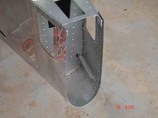
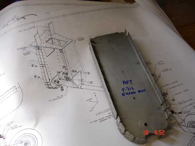
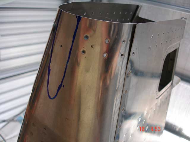
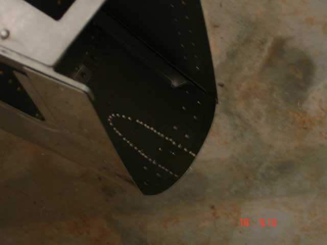
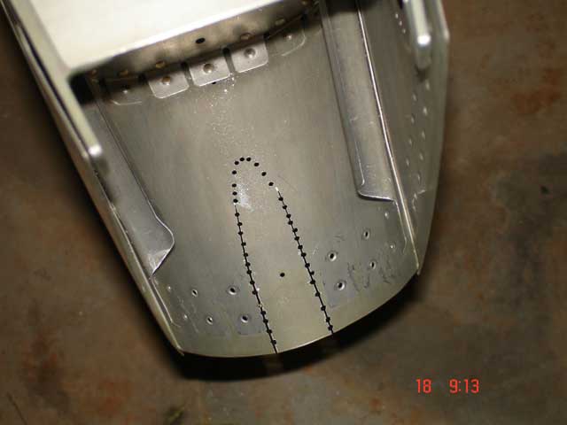
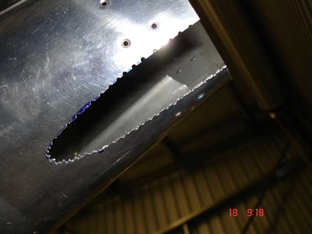
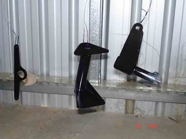
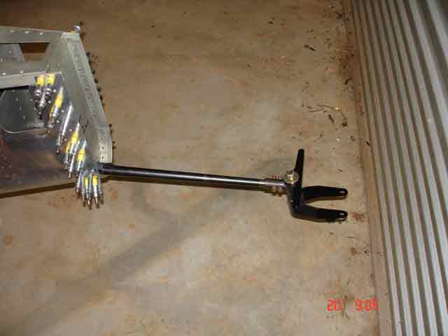
(17th March 2006) It was simple to drill out the few pop-rivets securing the rear bulkhead (F-712?) to the fuse skins, and slide it out of position. An elongated "mousehole" needs to be removed from the rear fuse skin to allow the tailwheel spring to extend from the rear fuse. I used the plans to make a template and sticky-taped this to the skin. Using the template I marked where the mousehole needed to be on the skin. I then used a #40 drill to drill out as much of the sheet as I could, and used a small saw to cut through these holes. I disassembeld the tailwheel spring assembly, and used metal spray cans to paint the unfinished components with undercoat and black enamel (last image). Finally this hole needs to be cleaned up with a file.
|
F-712 removed |
F-712 on the bench |
Mouse hole marked |
Mouse hole drilled |
Mouse hole sawed |
Mouse hole removed |
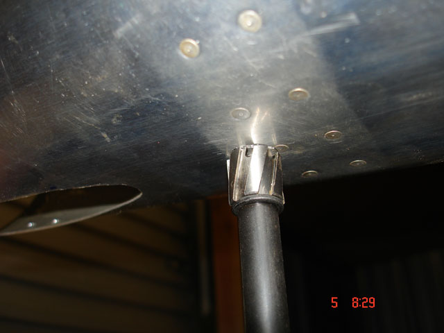
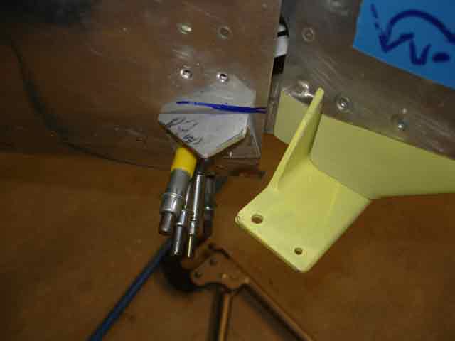
tailwheel mount drying |
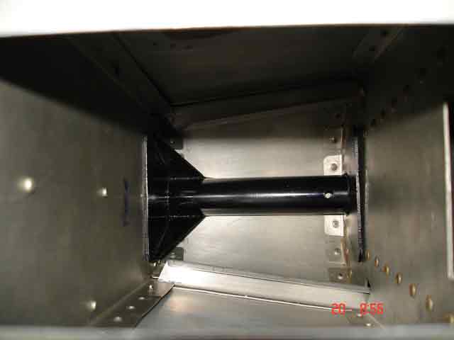
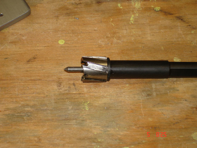
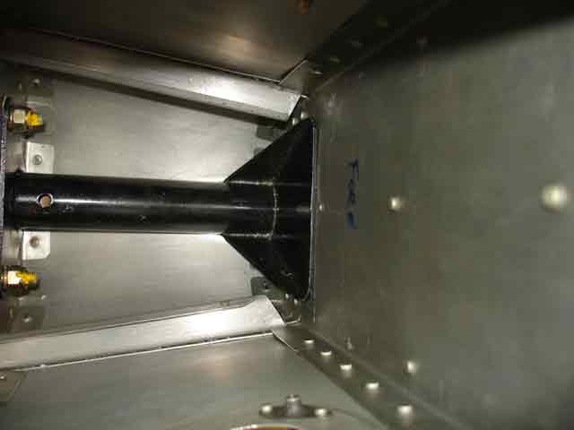
(19/20th March - 6th April 2006) I used flat and round file, followed by scotchbrite, to give this edge a smooth finish. The support weldment went into place against F-711 very cleanly, but was then impossible to fit the F-712 assembly back in place because of the tapered shape of the rear fuse. You have to "jiggle" it in, making sure you insert the top square flanges into the upper space so they can be coaxed back into position in the taper at the same time as you push the round flange assembly down into position. This MUST locate around the circular tube, which takes a little patience to do. To do this you must first have the weldment in position and insert the F-712 assembly top firstp. It took a bit of experimentation, frustration and cussing, but I finally got the bugger in place. The F-711 guide holes mark hole positions to match drill the weldment to F711 to 1/4" (AN4). The temptation is to drill from the rear at an angle, but to do so means you cannot get the drill at right angles to the bulkead (the weldment is in the way). The holes MUST be square for bolt head load-bearing reasons. Use a small drill (e.g. Sioux air drill) from inside the fuselage, where you can get the drill square to the surfaces. Finally, I used a sheet cutter to cut the socket hole for the tailwheel spring attach bolt/nut. First efforts were a little displaces - I had to enlarge the hole with a round file. In the end it all worked fine. I could rivet in place now, but I think I will wait, just in case.
|
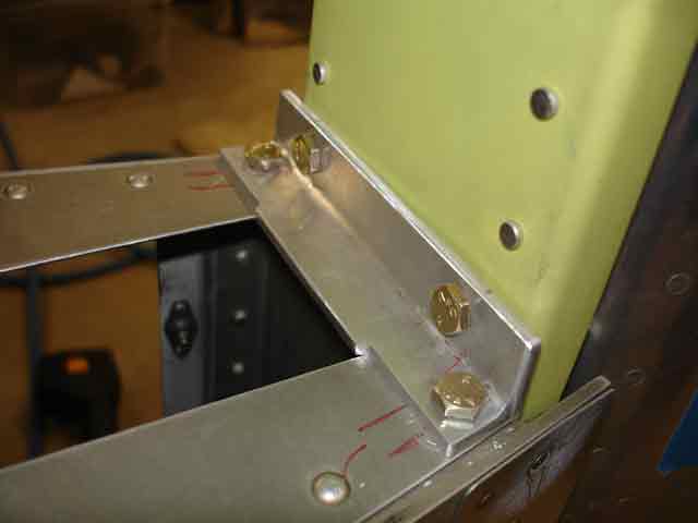
weldment in place but not secured yet |
with spring inserted - clecos ensure position |
Wow! a tailwheel! |
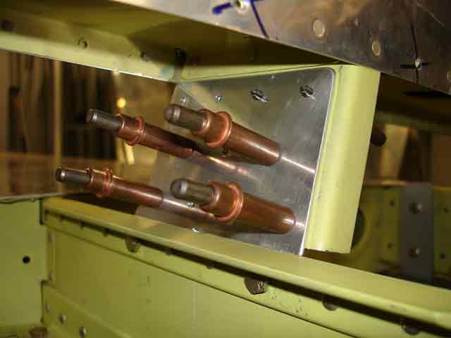
Bolt heads |
Sheet cutter |
T/W Socket hole |
Offset! |
(1st May 2006) The rear fuselage is completed when the rear elevator control stop, rudder control stops and inspection plates are completed and riveted in place. The rear fuse skins have the depressed areas to take two inspection plates, and these are pre-drilled to take K1100-6r6 nuplates and screws. You need to drill out and dimple or countersink these holes to take the nutplates and rivets as required. I countersunk the skins to take the flush rivet heads, and used the screws to locate the nutplates while squeezing the rivets. It all turned out OK as shown below. The rear elevator stop is fabricated from some 1 1/4" x 1" x 1/8" aluminium angle stock. This component is shown (rear elevator control stop) held in place with a small clamp, ready to match drll and rivet in place. Note that it also provides an anchor site for the Vertical Stabilizer.
|
rear inspecton plate location ready to dimple |
dimpled, ready to countersink |
Countersunk, rivets in place
|
dimpled, countersunk |
rear elevator control stop |
Empennage Attach (23 - 25 November 2006)
Horizontal Stabiliser Attach
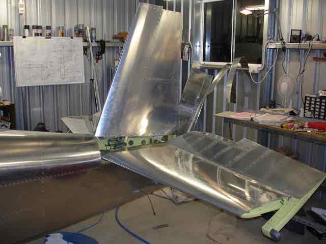
The time has finally come to try attaching the Horizontal Stabiliser (HS) and the Vertical Stabiliser (VS) to the rear fuselage. I confess to being a bit nervous because I am going to have to drill large #12 holes through the top longerons which support the flat deck on which the HS sits. The nasty part is that you cannot see the longeron ( it is hidden by sheeting) and so you need to measure, measure and measure again before drilling holes. If you bugger it up there is no second chance. The first three images show relevant parts of the drawings, mainly DWG 27A and DWG27. Red is HS attach, blue is VS attach detail. I first looked at my old preview plans, and was shocked to find som crazy dimension in there. I emailed Dan Checkoway ("Saint Dan"), and he shot right back with the good oil, pointing out that my old plans were wrong - when I checked the new large plans, all was kosher. Dan Checkoway is a true gentleman, one day i hope to meet him and thank him in person for his kindness and brilliant construction website.
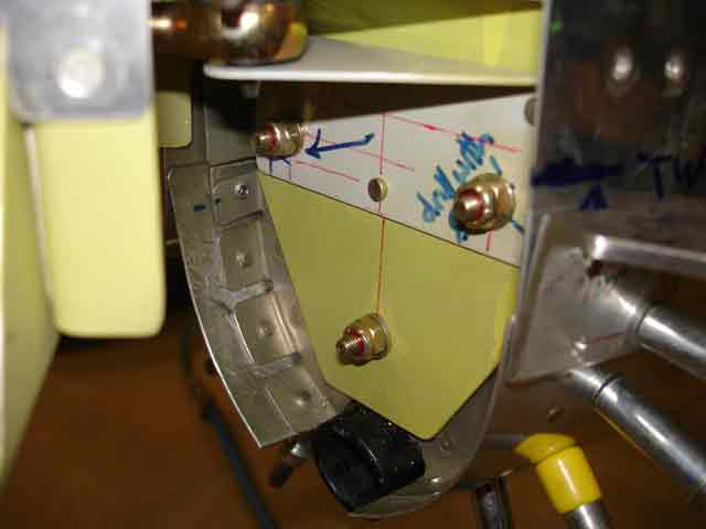
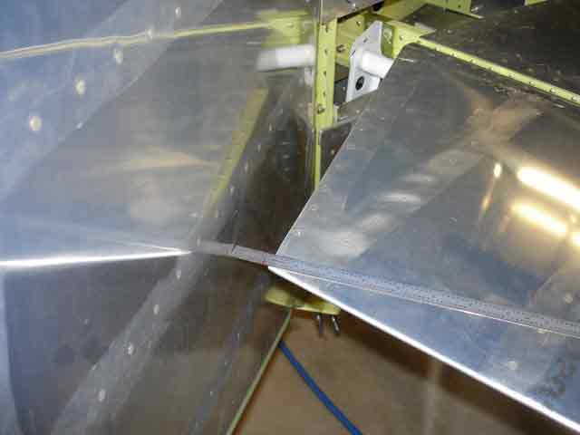
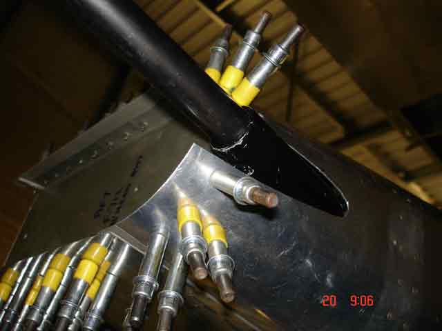
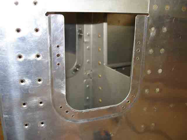
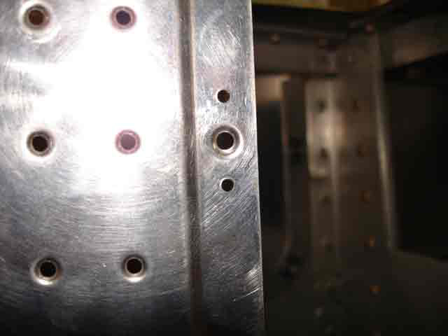
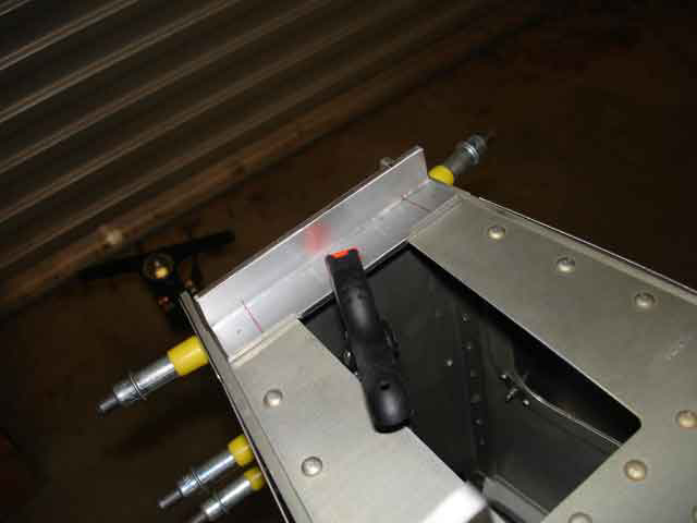
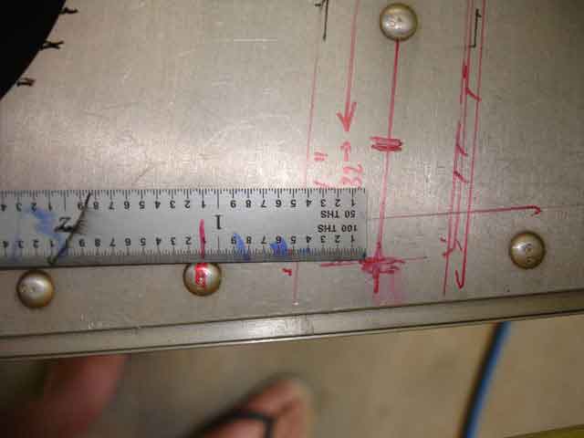
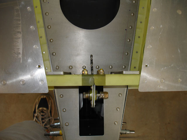
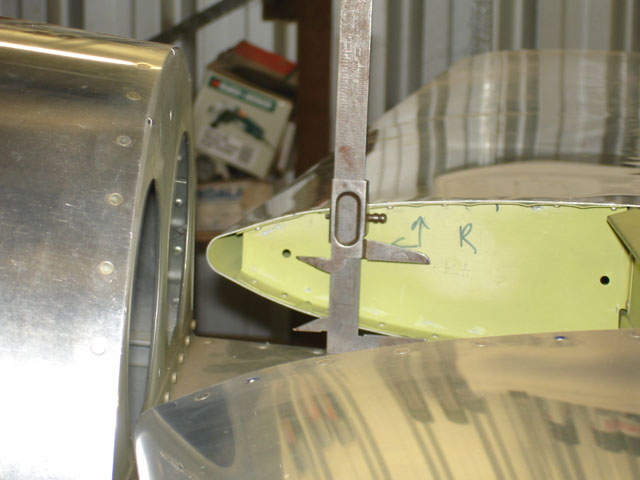
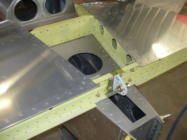
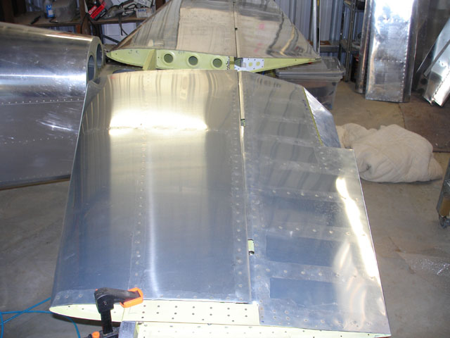
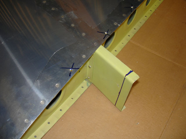
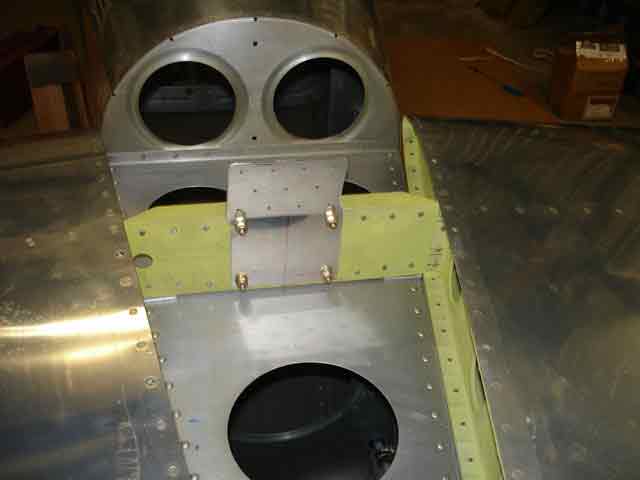
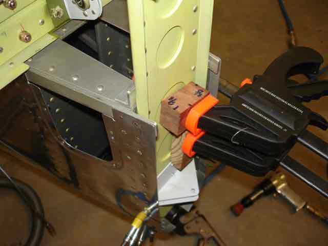
Image 4 shows how the rear spar aligns with the fuselage 2nd rear bulkhead attach bars, just where I left 4 empty holes in the spar. Image 5 shows the CRITICAL measurements of where to drill. The two most important aims are: 1. get the hole as close as possible to the centre of the horizontal flange of the longeron, emembering that 1/8" of its thickness is teh outside vertical flange; 2. Dont drill too close to the vertical flange of thew longeron - you have to fit washers and nuts in there. Image 6, 7 and 8 show me using a tape measure to get the distances from teh HS tips to the firewall equal (adjusting HS orientation until perfect).
|
HS front spar attach |
isometric (blurred) |
fron the side |
HS rear spar attach |
measure.. measure.. |
measure.. measure.. |
measure.. |
and measure.. |
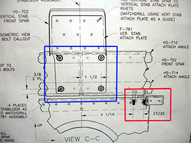
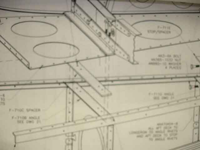
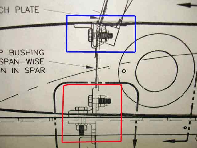
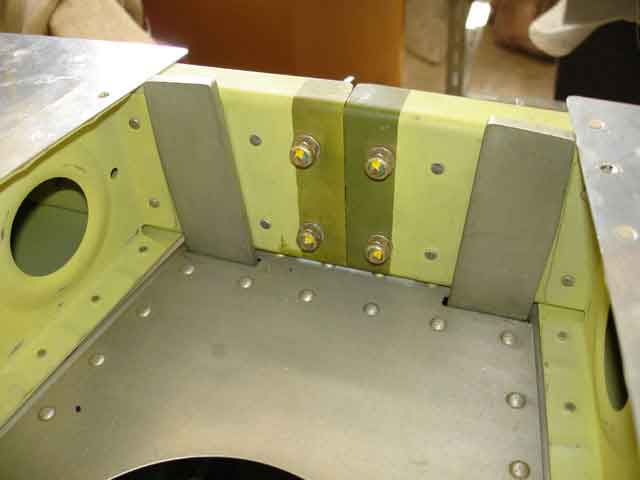
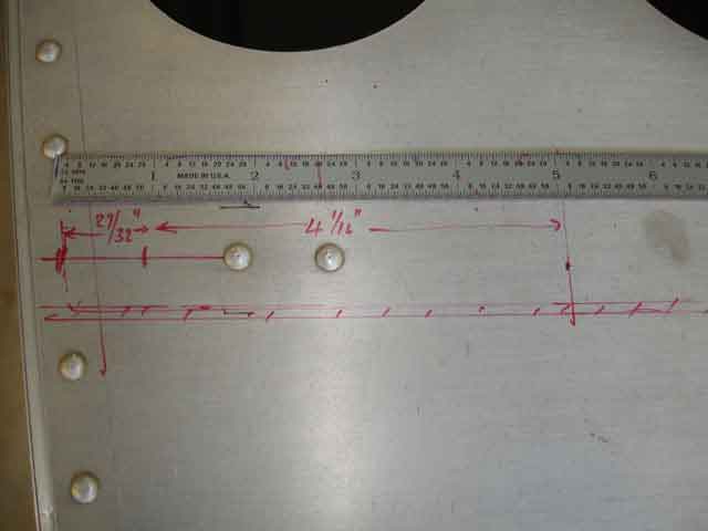
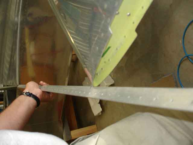
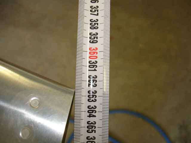
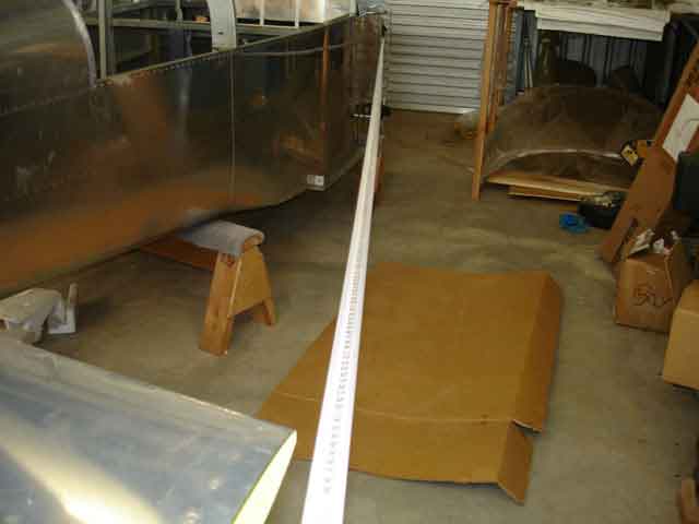
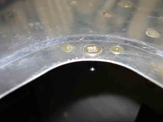
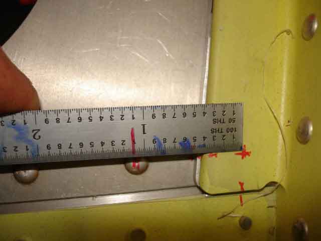
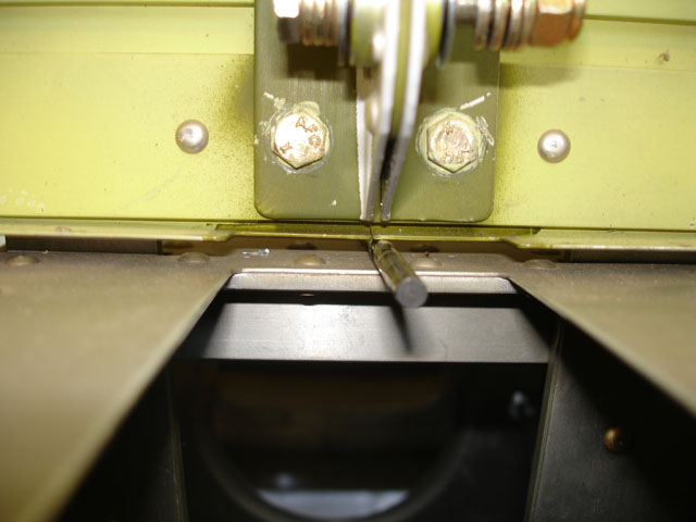
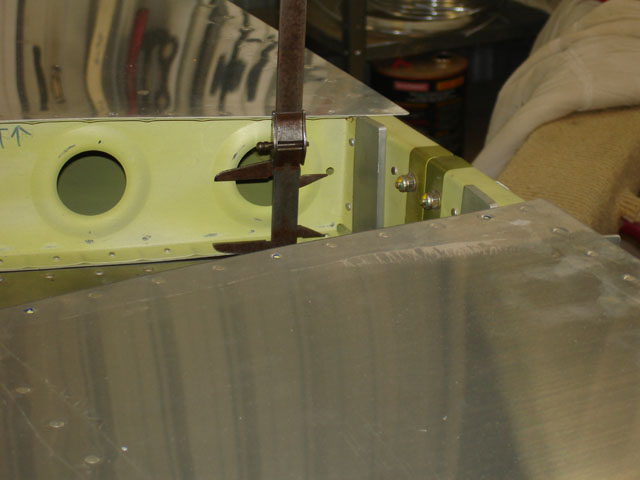
Image 1 below shows me measuring from an adjacent rivet head to where I intend to drill (red spot), and then removing the HS to check that this aligned with my measurements. It all looked good, so I got my long 1/8" drill out and went for itm drilling HS attach angle, shim, and longeron all at once (with everything clamped hard). The holes were each then carefully enlarged to #12 for AN3 bolts, and the HS bolted in place at the front spar only (not shown). Images 4 and 5 show a 3/16" drill inserted under the centre rear spar to set incidence (as Van's recommend). I used an old vernier caliper to check that all distances from rib tooling holes to longeron were equal (they were) confirming zero incidence. So I clamped and drilled, first 1/8", then #12, using clecos to hold everythihng together.
|
check measurements.. |
check measurements.. |
..DRILL! (4/32" pilot) |
3/16" drill gives |
correct incidence |
ff |
ff |
ff |
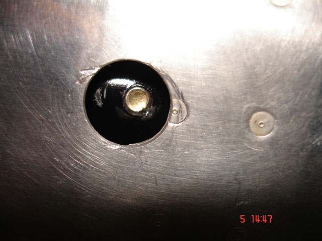
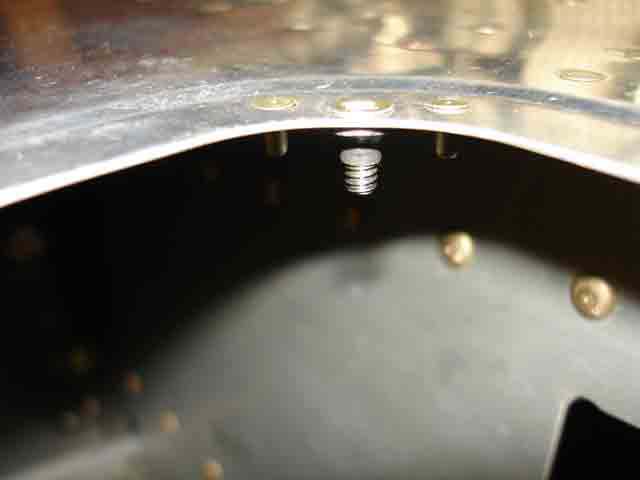
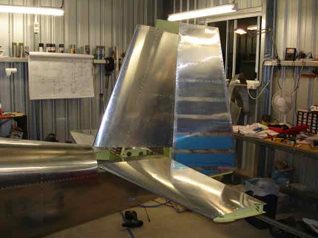
Images 1 and 2 below show the final outcome. Image 3 shows with the elevators attached, and when i installed and measured the rear elevator pushrod from bellcrank to elevator horn assembly (not shown). I have not drilled the inboard front spar attach holes yet (not shown), because I do not hae a suitable angle drill or long drill to get around the top angle of this spar and lin up on the hole. Will try to get a long #12 drill, or some other device for this. I do have a 3/16" angle drill, but it does not fit in the space (and drills a lttle over-size).
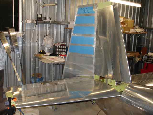
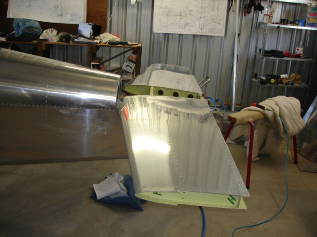
Vertical Stabiliser attach
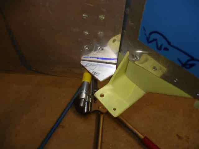
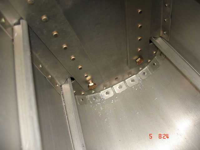
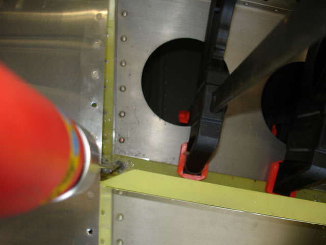
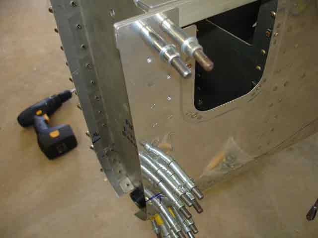
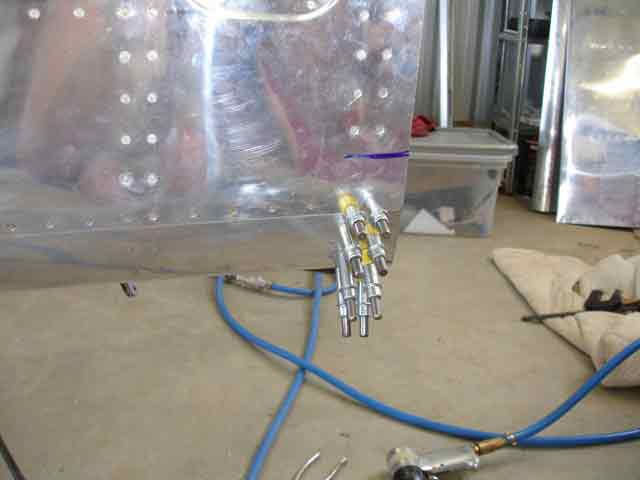
Image 4 shows the 5/8" you have to remove from the front upright of the VS - I used a hacksaw and finished with the Scotchbrite wheel. I began fitting the VS and realised that I had not finished riveting the rear bulkhead, to which it attaches, in position. Images 6, 7 and 8 show various stages of a brief session with squeezer and rivet gun/bucking bar. There are 8 or so rivets which fit under the tailwheel spring support and which I just cannot get to with a bucking bar. I will order some of Van's hi-strength countersunk pop rivets for these holes. No-one but another obsessive RV-builder will know the difference. This is one minor problem which quickbuilders have. Slow-builders make the rear fuse assembly in stages and I guess would not have the same restrictions.
|
HS is attached |
Looks good |
With elevators |
Remove this |
Then it just goes on |
But first finish rear fuse |
Inside fuse - can't buck |
these inside are them |
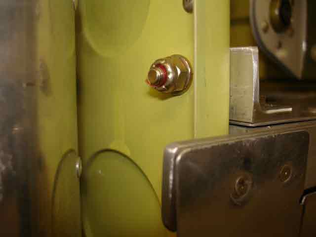
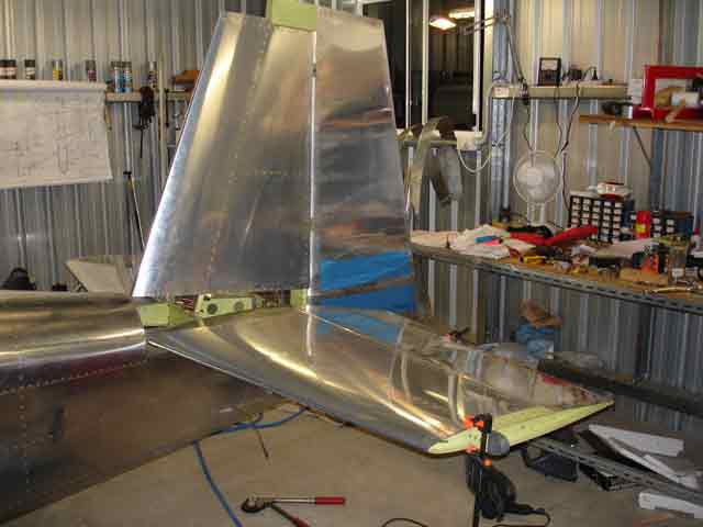
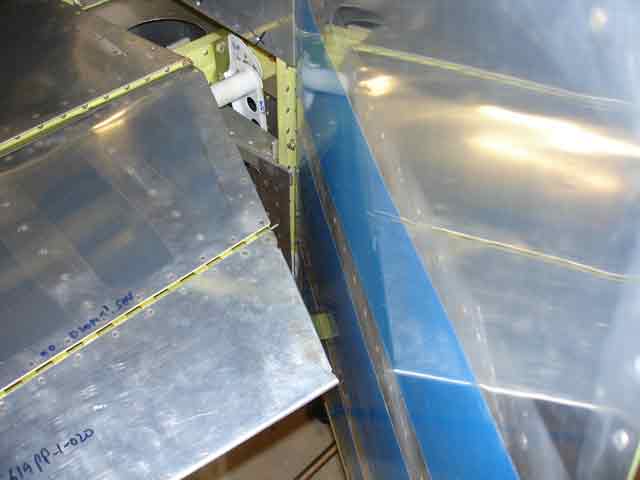
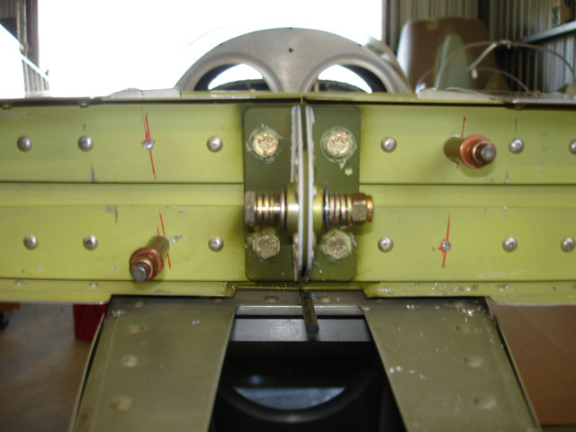
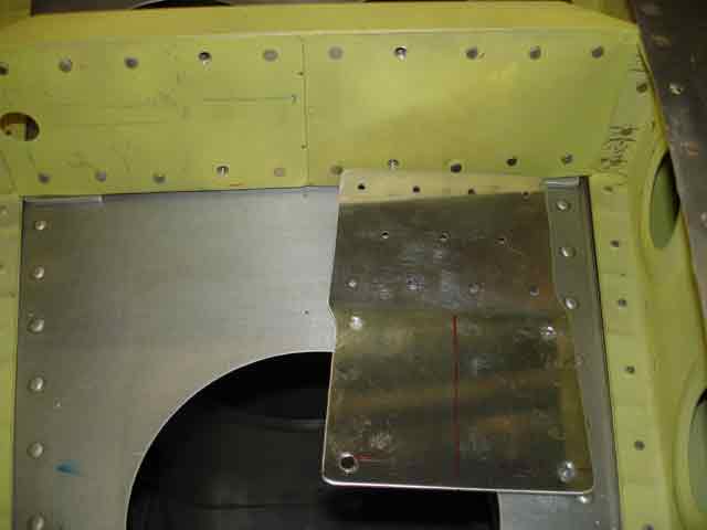
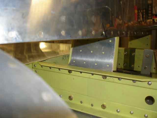
The front spar of the VS is attached to the HS front spar by a staggered attach plate. The stagger is there to introduce a 1/4" tilt to the left (same effect as right rudder) to counter the effect of the rotating prop wash. Image 1 below shows this plate lying behind the HS front spar, after it had been located and drilled. Image 2 shows it bolted into position. Notice the stagger. Image 4 shows the VS rear spar clamped into position - the vertical position is called out in DWG 27A. I centered it, and tilted it until my tape measure said it was vertical with respect to the HS. Image 4 shows the front attach plate and the VS front spar in place. I clampeed it all together and added the rudder (image 5). Looks like a REAL aircraft! Checking once more that the VS was still vertical, I then drilled the attach plate (image 6), and placed the "elevator up control stop" angle (image 7) in place between the VS rear spar and the fuse deck. This is a piece of aluminium angle which serves 2 purposes - it it is a physical "stop' for the elevator conrol horns going "up", and it attaches the rear fuse deck and upper longerons to the HS rear spar. I measured and drilled as required (there are still 3 universal rivets to go here, attaching this angle to the deck - these were added later). Image 8 shows the next sequence, adding the rudder control stops. These are two small angular shaped pieces of aluminium angle. They are rivetted to the fuse skin and stick out left and right under the HS and elevators. they provide a physical "stop", limiting movement of the rudder control horn to the left or right (image 8). You are supposed to position them so that, at full swing, the rudder trailing edge is no closer than 1 1/8" from the elevator trailing edges in neutral position. My separations were more like 7/8" on each side. I think I will add a little rubber sheet to each surface of the control horm - this will provide a physical "buffer", and reduce the swing of the rudder to within spec.
|
VS front attach plate |
attached at front |
clamped at rear, adjust |
this will be rivetted |
All looking good |
attach plate drilled |
elev up control stop |
rudder control stop |
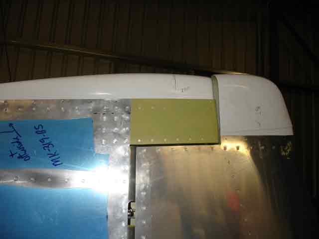
I spent quite a bit of time checking rudder swing. It was very free with no binding, but the maximum movement was about 3/4" greater than spec. Vans instructions call for a minimum space of 1/18" between rudder and elevator trailing edges - mine was a lot smaller, about 3/4" separation (images 1,4 and 7). I drilled the lowest rudder rod end bearing support (image 2) bracket, and checked the elevator stop angle (image 3), while the rudder and elevators were in position (images 5&6). I set up the VS deflection to the left at exactly `1/4", and drilled the front support plate. Finally I fitted the upper rudder and VS fiberglass trims (image 8 below), just to see how much more work is required. I think I will delay fiberglass until all the aluminium work is complete (Il procrastinando!!). With everything drilled, bolted and measured ok, all that is left to do is to finish these loose bits, prime and store for final construction. Woo Hoo!!
|
rudder control stop RHS |
fuse skin near tailwheel |
elevator stop bolted |
a bit close, 1 1/8" please |
all done |
other side |
too close |
need to do this later.. |