Rudder control hardware
1. Rudder bar weldment and brake assembly
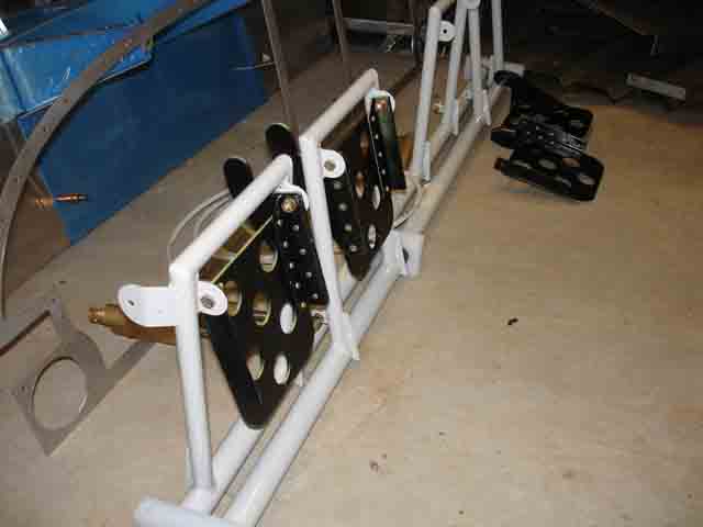
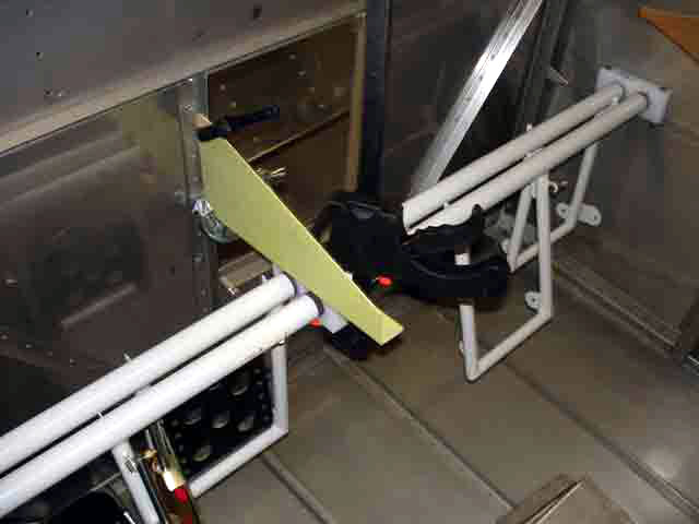
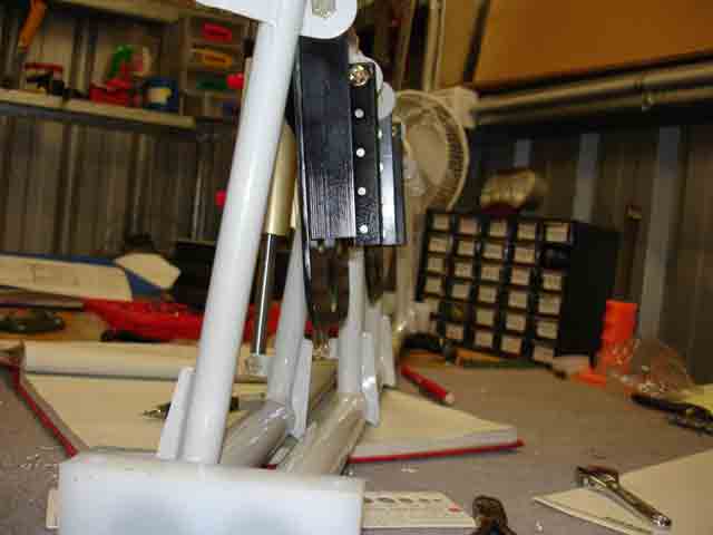
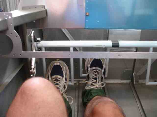
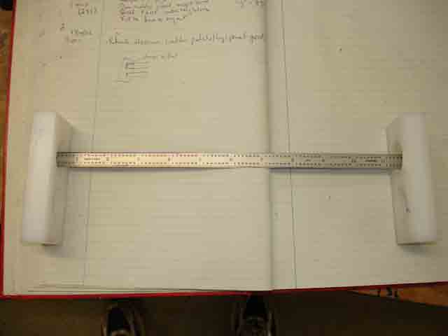
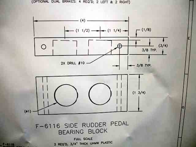
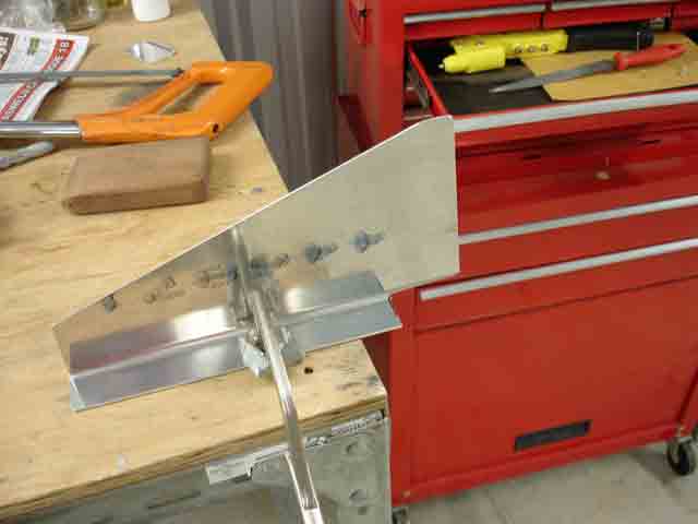
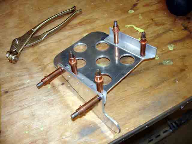
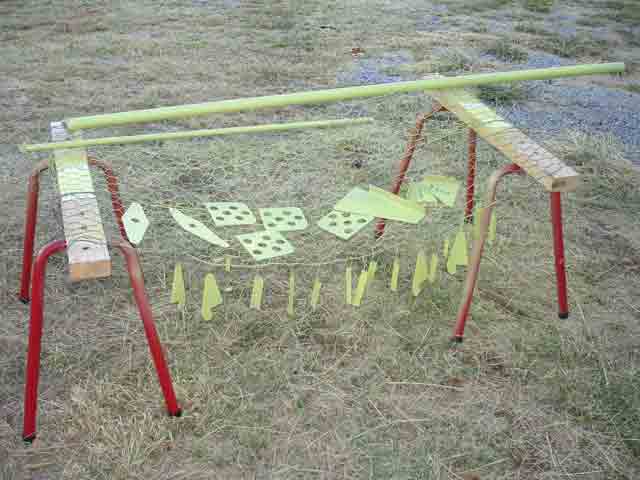
(17th April 2006) The rudder is controlled by means of two powder-coated steel weldments which fit into the foreward fuselage, just at foot level. Each footrest has bolted to it a pedal which, when pushed foreward, compresses a master cylinder activating the brake on that side. The weldments lie across the fuselage as shown in the first image - I did this to test for adequate knee room when finding the best position for the rudder controls. They are supported by three teflon bearings: at each end of the shafts, one is bolted to a longeron. A third is attached to an aluminium plate suspended from the firewall. In the second image I have placed a ruler between the teflon bearings, with its square end flat against the inside surfaces. Notice that the bearings are NOT square. The large holes bored into these blocks lie at a slight angle, so as to compensate for the taper of the fuselage longerons to which they are bolted. This is seen in the image of the drawing (image 3), but not mentioned in the construction manual. You could really stuff up here if the bearing blocks were in the wrong position or orientation. The next image shows the piece of angled Al sheet which will support the centre bearing - with a notch removed for the firewall inset. The following image shows the basic pedal construction. I primed all the bits (brake pedals, tank support bracket components [see 2.1 above], elevator push rods and bell crank bits), and even painted the brake pedals - they will see a lot of use I hope. Note I used a spray metal undercoat and black enamel for the two steel tank support brackets. Rust prevention.
|
Rudder controls - good knee space |
Note blocks are NOT square |
The drawing shows why |
Trimming central bearing support |
Brake pedal construction |
I decided to prime and paint |
Fitting pedals. Note brake cylinders |
Auto enamel for steel tank supports |
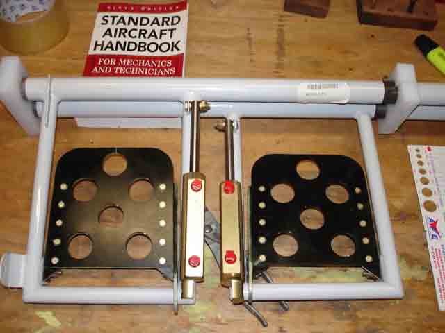
(20th April 2006) The angle that the brake pedals makes with the rudder bars is critical for obvious reasons. Set them at different angles and you will always have one brake on before the other. Set them too far back and you will ride the brakes when taxying. Set them too far forward and you might not be able to reach them. I managed to scare a few people on the Australian RV-7 Builders' email list by naively asking whether I should bolt the brake pedals parallel to the rudder bar frame. The first pic below shows why this is a stoopid suggestion. The rudder bar pivot rods lie one in front of the other. To have the bars in line, the frames for left and right bars must be positioned at different angles in the fuse. So the brake pedals must also be positioned at different angles relative to the rudder bar frames. I have decided to wait until it is absolutely necessary to drill these holes, and then hopefully to do so with my feet in position to get the best angle.
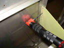
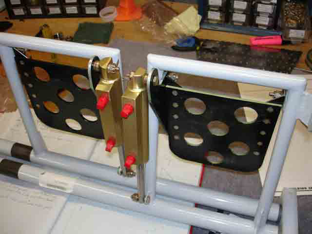
(4th May 2006) Today I took the plunge and completed the rudder pedal/brake assemblies. Image 2 below shows the central teflon bearing and its support angle clamped in position. I used the #40 angle drill (image 3) to match drill rivet holes in the firewall inset angle. I then took the whole assembly out and set the pedal angles to an angle so their tips lie about 1" in front of the left rudder bar frames - I got this dimension from a few owner-builders in Sydney. I set the right pedals to be exactly parallel to the left, and marked where to match drill the master cylinder holes to the pedal lugs. It was right dead smack in the centre of the lugs (image 4)! I will not really know how well this will work till the first taxi, but it looks good!
|
Rudder bar frames & brake pedals, upside down on the floor |
Central support in place |
Using angle drill to match drill rivet holes |
Getting Brake pedal angles just right |
Note brake pedals parallel |