Elevators
The RV-7 has two separate elevators, each linked to its own elevator control horn, bolted together and supported by a central bearing. The structure of each elevator is quite different, due to the fact that one has a trim tab and the other has not. Elevator construction is similar to the rudder in that the skins need to have stiffeners attached. Otherwise it is very different in that there is a single folded skin for each side, and there is the complication of the trim tab, trim servo (or cable) mount and accompanying reinforcement structures.
1. Identifying Stiffeners
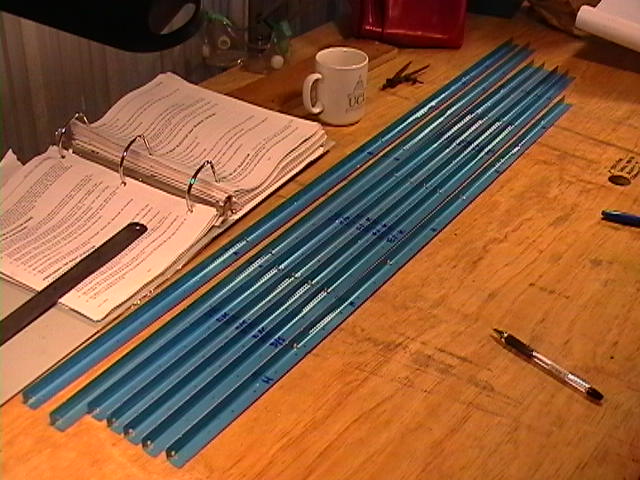
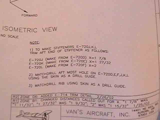
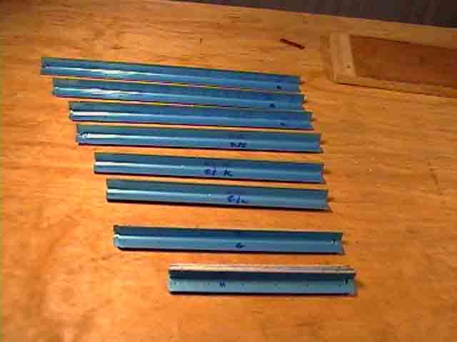
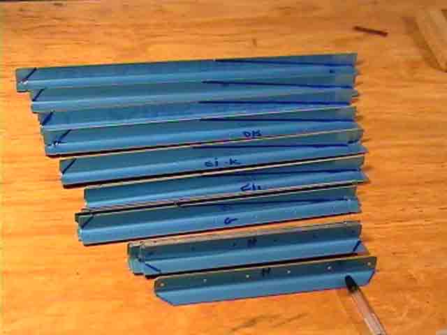
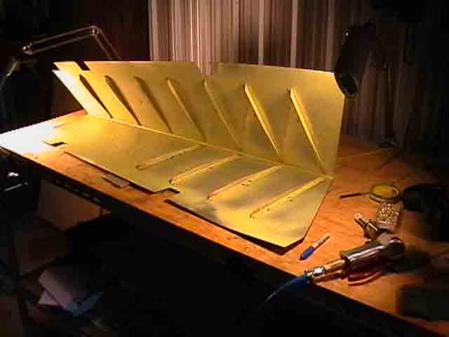
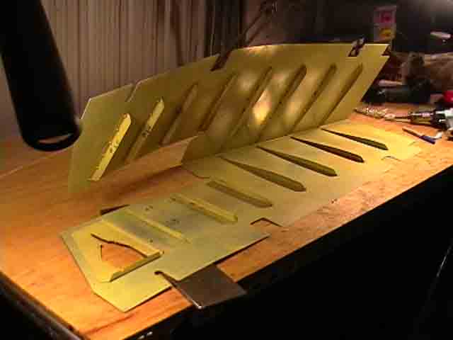
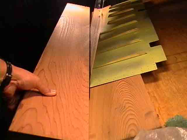
The elevator stiffeners come packed as seven lengths of angle aluminium, pre-punched with holes dividing them into the appropriate lengths. What the plans do not tell you clearly is that there are subtle differences between left and right sides. Count the stiffeners in the images below. Yep, there are seven on the right hand side, and eight on the left! Hence, the middle stiffeners are shorter on the LHS,and have to be trimmed accordingly. The appropriate dimensions are shown below in "Note 1". You have to be really careful here. It would be quite easy to snip the angle in the wrong direction and end up with a load of useless aluminium angle of the wrong dimensions!. First I cut out the stiffeners so their lengths were correct, and I placed similar stiffeners together to check dimensions and numbers.
|
seven lengths of angle |
different stiffeners marked |
The plans show stiffeners |
arranged on each side |
how to trim stiffeners |
stiffeners rough cut |
2. Cutting stiffeners
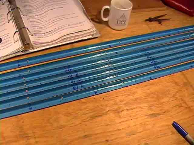
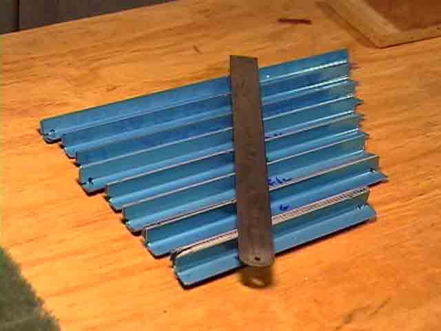
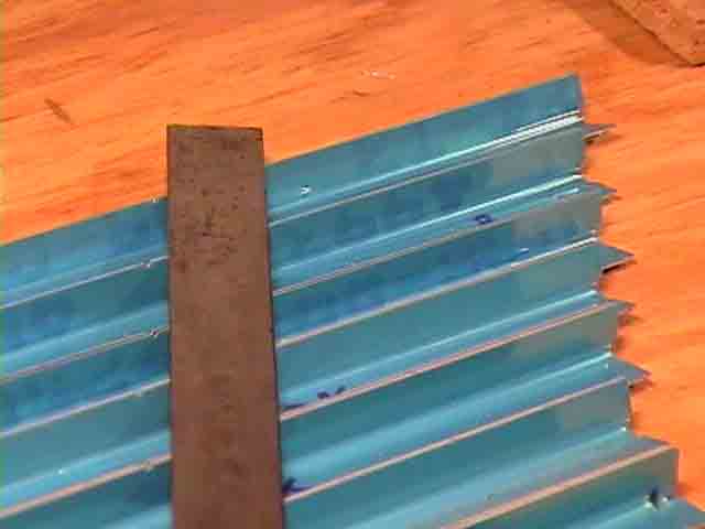
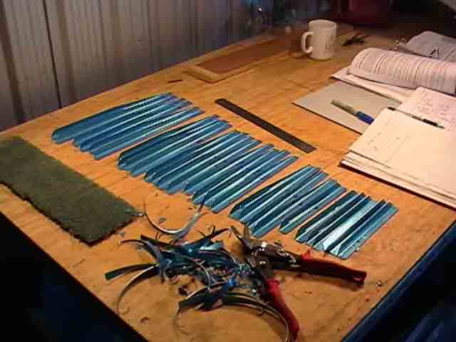
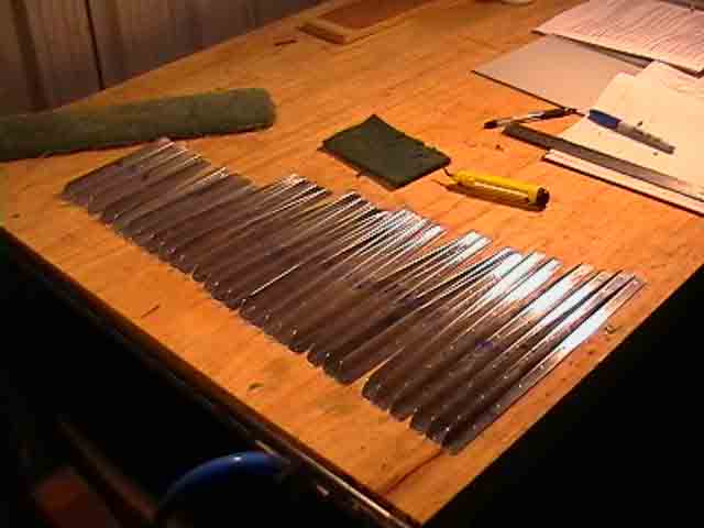
Once you understand how the stiffeners are organised, you can lay them out to make sure you have them in the right orientation. There are small notches in the surface without the holes. These tell you where to start the taper. The taper finishes at the end of the stiffener. I have laid a ruler close to these notches so you can see how they all line up.Look at the high mag view to see the notches aligned to the left of the ruler. The taper goes from these notches to the right. In the next image I have used a (blunt!) "Sharpie" pen to draw a line where the cuts will be to form the taper. Notice that the small stiffeners (H) have no taper, as per the plans. These are positioned in the area forward of the trim tab, and so do not need to be tapered. The stiffeners were trimmed with the Wiss snips (which are great!), the blue plastic was removed, and the edges of each were smoothed with the Scotchbrite wheel. It takes a while to do all this. Finally the stiffeners are clecoed in position on the inside of each skin, and a #40 drill is used to drill out each hole to its final dimension.
|
notches aligned |
high mag view |
marked up |
stiffeners trimmed |
ready to cleco |
drilling skins and stiffeners |
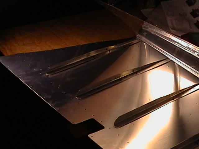
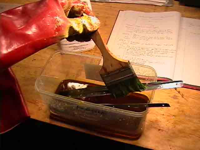
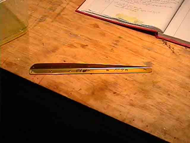
3. Deburring, dimpling, priming, riveting stiffeners to skins
This is repeated for both skins, taking care to use the right stiffeners on each side. Then what seems like a zillion 3/32" holes each need to be deburred and dimpled. It is difficult to get the C-frame tool dies near the most aft stiffener attach holes. So I used the Avery "Pop-rivet" dies and my trusty pop-rivet gun. Basically the pop rivet gun pulls on a nail and squeezes the dies together. Minimum space is required inside the structure. The results were good - I am glad they included this tool in the Avery empennage tool kit. All stiffeners and both skins were treated with 1) detergent/Scotchbrite pad rinse and light scuff; 2) Alumiprep bath or painted on; 3) Alodine 1200L anti-corrosive chromate finish. Finally all stifferens and both skins were given a very light spray coat of Sterling 2-part Epoxy primer/sealer. The back-rivet set was used to fasten stiffeners and trim brace plate to the skins.
|
stiffeners clecoed |
pop-rivet type dimpler |
alumiprep & alodine |
gold alodined stiffener |
Right stiffeners done |
Left Stiffeners & trim brace |
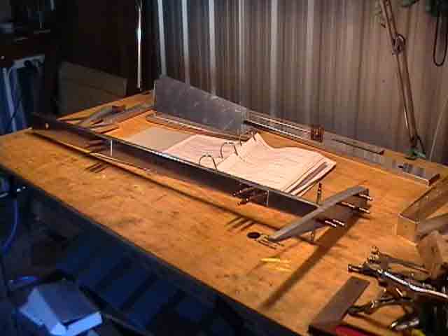
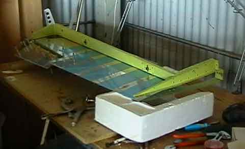
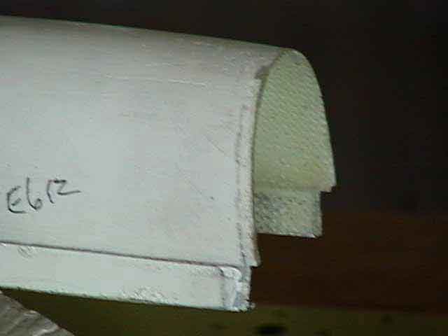
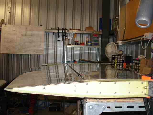
4. Brake and trailing edge bend
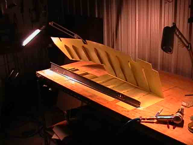
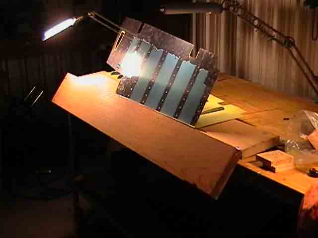
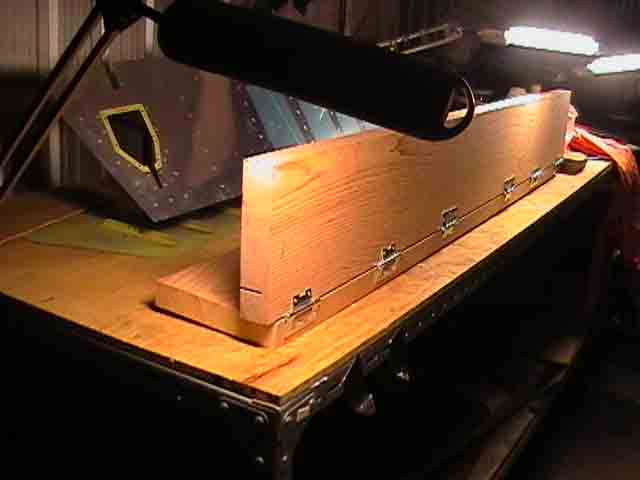
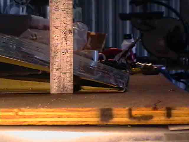
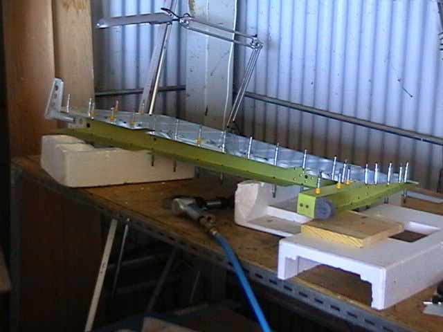
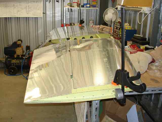
The next step is to bend the trailinge edge. The image with the front spar in position shows just how much bending is required - the top skin must align with the upper flange of the spar. This is performed with a "brake" made of two hinged pieces of straight dressed timber, separated by a gap of about 1/8" (3mm). On the advice of another builder (Bob Barrow), I made my brake wth the two pieces of timber hinged at right angles to each other, rather than parallel, as in the Vans instructions. The bending surface will be the 2" width of the upper length. This means that I can se the surface angle being bent and hopefully ensure the bend occurs evenly and right where it is needed. I bought a length of 3mm diameter carbon rod at a hobby shop. This will be taped into the angle to form a minimum curvature template. I tried bending a piece of scrap first. I found that, if the angle is too sharp, the Aluminium work-hardens and starts to split. It is obviously very important not to over-bend and end up with too "sharp" a trailing edge. The final image shows the end result - a trailing edge diameter of about 3/16".
|
Trim brace outside view |
Front spar in position |
Brake and skin |
Brake construction |
Ready, rod in place |
after bending - enough? |
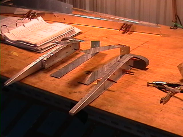
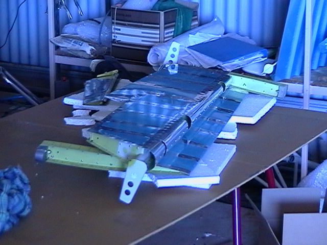
5. Counterbalance ribs and control horns
The next sequence involves the counterbalance weights. These are attached to the outer ribs of both elevators by means of counterbalance ribs and skins. The first image shows the right elevator skeleton clecoed together. the next image shows BOTH (L&R) counterbalance weights and the ribs and skins which support them. In the next image, one counterbalance is fastened into its skin/rib assembly (with clecoes). The two small holed at the front are use to locate a #12 drill which bores holes for the bolts which attach these weights in position. Next the control horn is positioned with clecoes and match-drilled. Once everything is drilled, dimpled, alodined and primed you are ready to tivet it together. Be careful NOT to dimple the upper flange of the inbord spar of the left elevator. This is where the piano-hinge is to be attached. The spar flange holes are countersunk to accept the dimpled skin holes above, and line up snugly with the flat hinge plate below. You need care here. Don't try to dimple the hinge. Study Drawings carefully.
|
Skeleton |
Counterweight bits |
Counterweight assy |
Control horn |
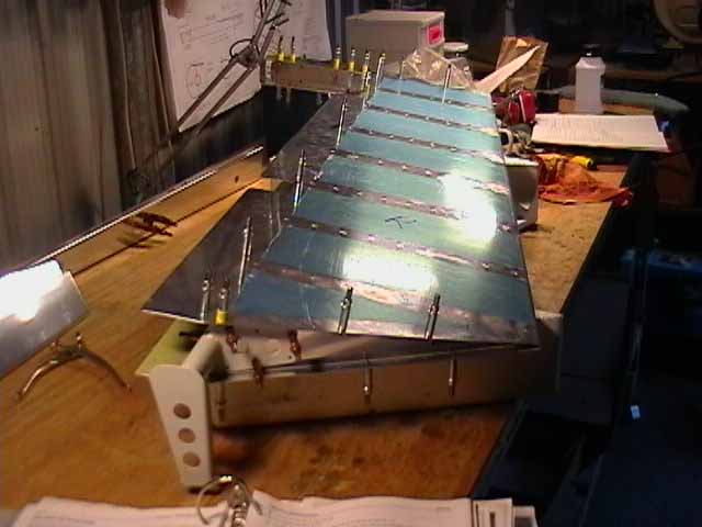
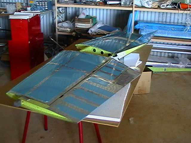
6. Skeleton and counterweights
The sequence of construction is to first assemble the elevator skeleton and control horns, riveting together the spar and the end ribs with the horn. Next the counterbalance skin is riveted to the main skin by two key flush rivets which would otherwise be inaccessable after final assembly. Then the skeleton is slid into the skins, holes are lined up and final finishing checked before final assembly. I found the counterweights needed to be trimmed slightly to fit easily between their skins and rib flanges. I just removed enough so that everything fitted together snugly. The fibreglass tips need to be trimmed so their forward edges fit neatly around the weights and between counterweight and counterweight skin. These tips are just a fraction too long, but final trimming should be made AFTER final assembly.I have decided not to bother with filling the minor gaps between glass and aluminium. I will just rivet the tips and and use microballoons to close off where necessary.
|
skeleton on skin |
cleco every 3rd hole.. |
..and rivet in-between |
Trim weights |
Trim glass tips |
Fit tips and weights |
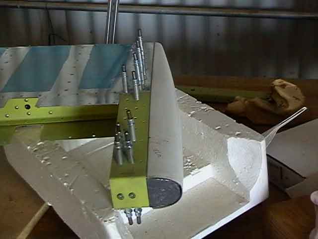
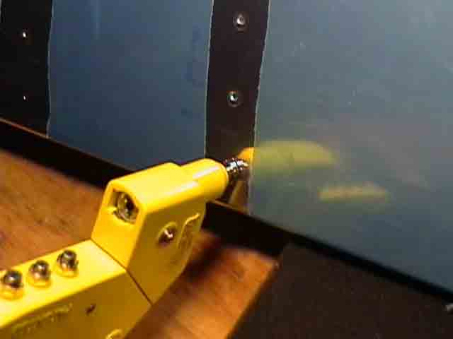
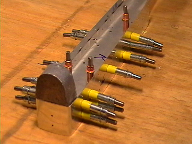
7. Trim Servo Mount
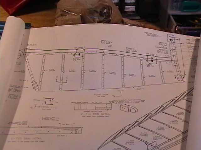
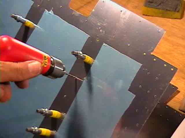
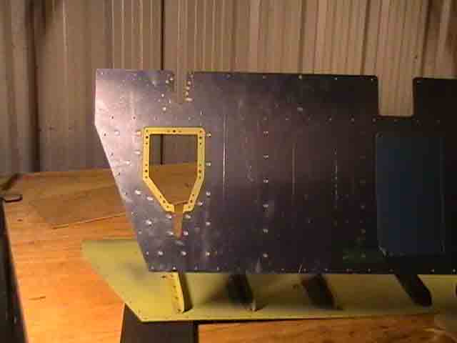
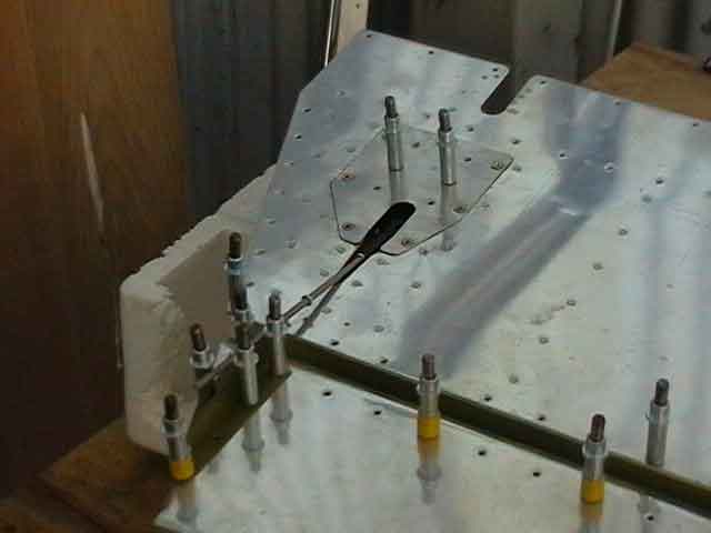
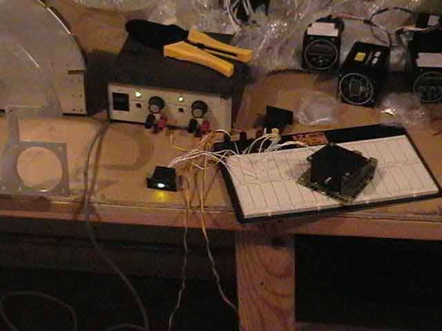
There is very little information given in the instructions about the trim tab and trim servo construction. I have the Ray Allen Electric Trim option, and these notes relate to this construction. The trim tab is driven by a servo which is mounted on a plate which attaches to the lower left elevator by seven screws. These mate with seven nutplates which are riveted to a reinforcement plate which in turn is riveted to the lower elevator skin. Belatedly, I now know that these 7nutplates should be riveted to the reinforcement plate BEFORE it is riveted to the skin. Since I had not done this (I followed the instructions!) I had to use my backriveting set plate, placed judiciously so that it did not overlap the skin (see first picture below). The plate here abuts the overlap between skin and reinforcement plate, leaving zero gap between plate and flush rivet head. I had to move the edge of the back-riveting plate around to do this for all platenut rivets (second and third picture below). It worked out OK (see "Mounting plate in position" below). Finally, before trimming the theaded rod which actually moves the trim tab, I set up the servo with its switch and LED indicator ("testing servo operation" below) so as to find the "middle" position for the servo (see indicator LEDs in last picture). I will try my best to trim the rod so that the trim tab is in neutral position (lined up with elevator trailing edge) with the servo in this middle position.
|
back-riveting mounting nutplates |
One nutplate ready to rivet |
nutplates in position to rivet. Note backplate |
Mounting plate in position |
testing servo operation |
My first real criticism of the RV kit is the lack of information about building the trim tab. I botched mine and will probably replace it if I get a chance. The problem is that you are told to bend the trailing edge before attaching control horns and tab spar. Once the skin is bent there is no room at all to get a bucking bar or rivet squeezer inside the tab. I ended up having to waste a heap of MK- flush pop rivets attaching the trim tab spar to the bent skin. I also managed to over-bend one of the side tabs, cracking the Alclad skin. I cut this away and replaced it with a small "riblet", but this turned out to be a little too wide, so the tab does not line up with the rest of the elevator as cleanly as I would like. Next time I would try riveting the spar and control horn to the lower skin BEFORE bending the trailing edge, and use a bigger radius on my bending blocks.
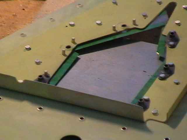
9. Final Assembly and leading edge folds
RTV, Proseal or other goo has to be spread between the stiffeners at the aft angle of both elevator skins. This is to inhibit vibration and skin cracking which apparently has occured without this measure. I used 'blue" automotive gasket RTV as suggested by Dan Checkoway. Then most of the skin rivets can be either squeezed or shot. I shot most of them by myself and only had to drill out a couple. I cleco every third hole, and use rivet tape to hold rivets in position and protect the skin surface. Once complete, clecoes and removed and the remaining holes completed. I rolld the leading edges with a 1" steel shower curtain. These were more difficult than the rudder, even though I rolled them in stages. Once the elevators were attached to the Horizontal Stabilizer, the expected interference was observed between counterbalance sections and HS skin. I marked out and removed the offending Alcld, using a drill and small hacksaw to remove all but 1mm of material. A small file was used to get the final smooth surfaces. The result was two freely swinging elevators. The left elevator is a little HEAVIER than it should be (it falls down. not up). I will need to use some of the right counterbalance material to add a very small amount of lead to the the right. I guess I must have removed too much lead on this side (or it may have been too much primer). It is only a few grams.
|
ready to rivet |
cleco every third |
rivet tape protects |
leading edges rolled |
the usual problem |
how's it hanging? |
Elevators and Empennage basically complete 18th August 2005!
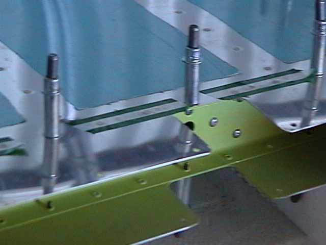
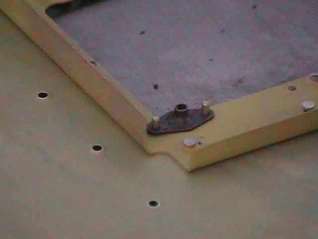
10. Drilling elevator control horns, and adding fibreglass trims
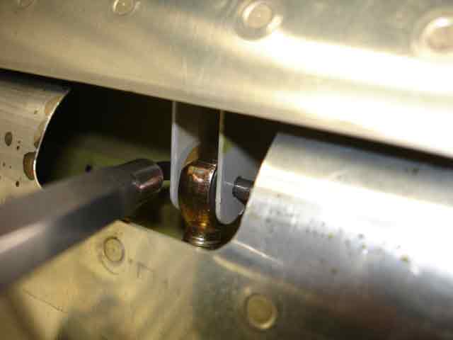
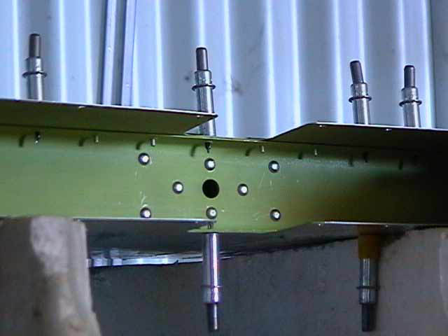
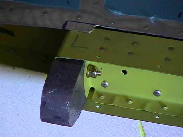
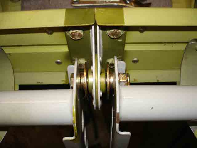
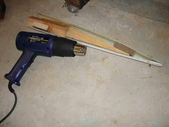
(30th April 2006) After months in storage I dragged out the horizontal stabilizer and attached the elevators. After confirming clearances and distances were to specification, I used a 1/4" drill placed in the central bearing to mark where to drill each horn. The instructions recommend using a piece of tubing as an alignment tool to drill, but the 1/4" drill worked well and, operated carefully by hand, did not damage the bearing surfaces. The elevators were removed and drilled where marked. Image 2 shows the AN4 bolt (with the wrong large washers in position - the correct plated washers are now in place). The elevator horns are individual weldments - the apparent slight misaligment is correct, it is due to slight shape differences between weldments. Next I will need to drill the holes where the pushrod attached to the elevators - will devote a lot of time to this to ensure correct alignment. The third image shows a heat gun used to expand the shape of the elevator counterweight edge trim, in preparation for pop-riveting to the elevator trims in place.
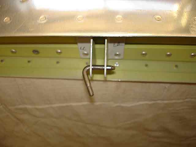
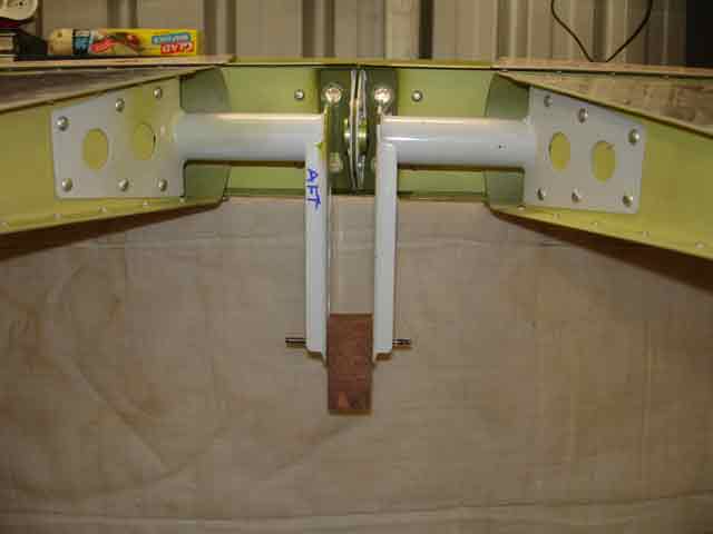
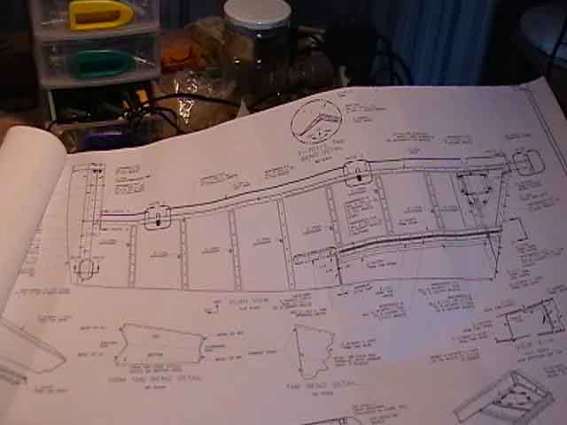
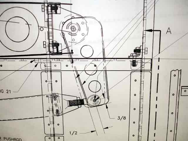
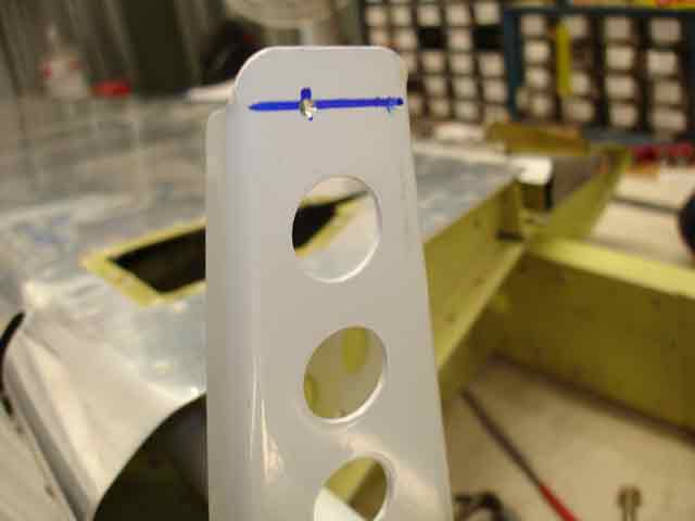
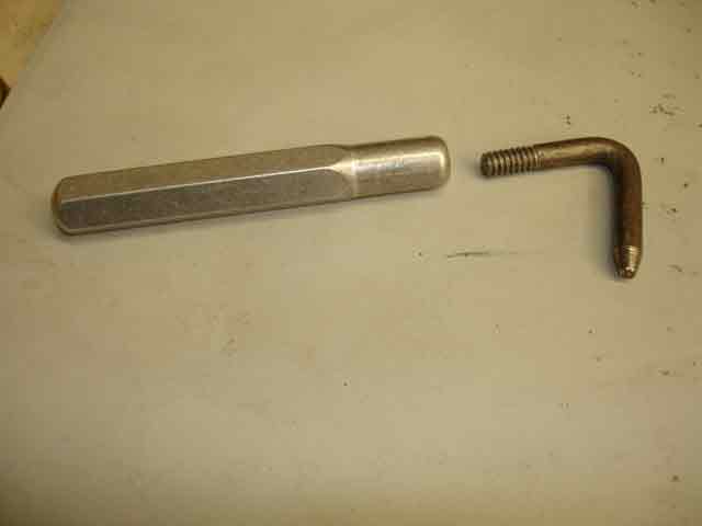
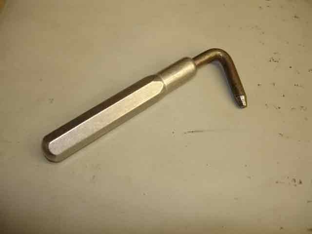
(31st July 2006 - 3 hours) I have been too busy doing other stuff. First time back in th workshop for 6 weeks so i decided to srill out the elevator control horns for the AN3 push rod/control rod bearings. The relevant drawing is in image 4. You align the elevators (image 6), find the aft-most control horn, and drill a #30 hole 1/2" from the front and 3/8" from the lower edge (image 5). Attaching elevators and other controls is made very easy by using the excellent little devices from Avery shown in images 7 and 8. They consist of a small piece of 3/16" rod (AN3), bent and threaded on one end. The thread screws into an Aluminium handle. When threaded in place, it is very easy to fit this little piece of rod into the rod end bearings attaching the surface - in this case, attaching elevators to horizontal stabiliser.
|
Align elevators in preparation to drill control horns |
Centre bearing (wrong large washers) |
Heating fiberglass to get the correct shape |
Elev contrl horn drawing
|
Measured ready to drill pushrod connect
|
Aligned again
|
These gadgets are great
|
The AN3 hook screws in place
|
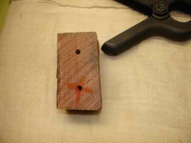
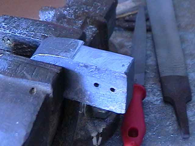
The first image below shows one of these devices fitted in place in an elevator bearing bracket on the horizontal stabiliser. The next image shows the same view, but with the elevator in place, and the rod device manouvered into position through the gap in the rolled leading edge of the elevator. With the aluminium handle in place, this takes only seconds to do, compared with minutes if AN3 bolts were used. Of course the bolts will go in place eventually! Once the elevators are positioned, the pilot hole is drilled in the aft-most control horn (left in my case). I then made a block of hardwood which slid snugly between th elevator horns. Using a perpendicular drill-press, I drilled this block with a #30 3/32" drill. This block and the resulting hole were used to guide a #30 drill through the first hole and across to the other elevator control horn to drill another pilot hole. These hole MUST be square, otherwise the elevators will not be aligned in final assembly.
|
It temprarily attaches the control surface hinge |
Like this - easy to disassemble |
Here is my hardwood spacer for drilling contrl horn |
Here are both pilot holes drilled |
|
|
|
|